ODrive Calibration
Calibrate each motor individually on the bench before assembling the robot. This sets the motor parameters and verifies the hall sensor connections. Do this once per robot (or after a config reset).
Warning
The motor will beep and spin during calibration. Clamp the wheel securely — never hold it by hand.
After Calibration
Once both wheels are calibrated, proceed to Assembly to mount everything onto the robot frame.
Part A: Bench Hardware Setup
Before running any software, set up the ODrive and one wheel on the bench.
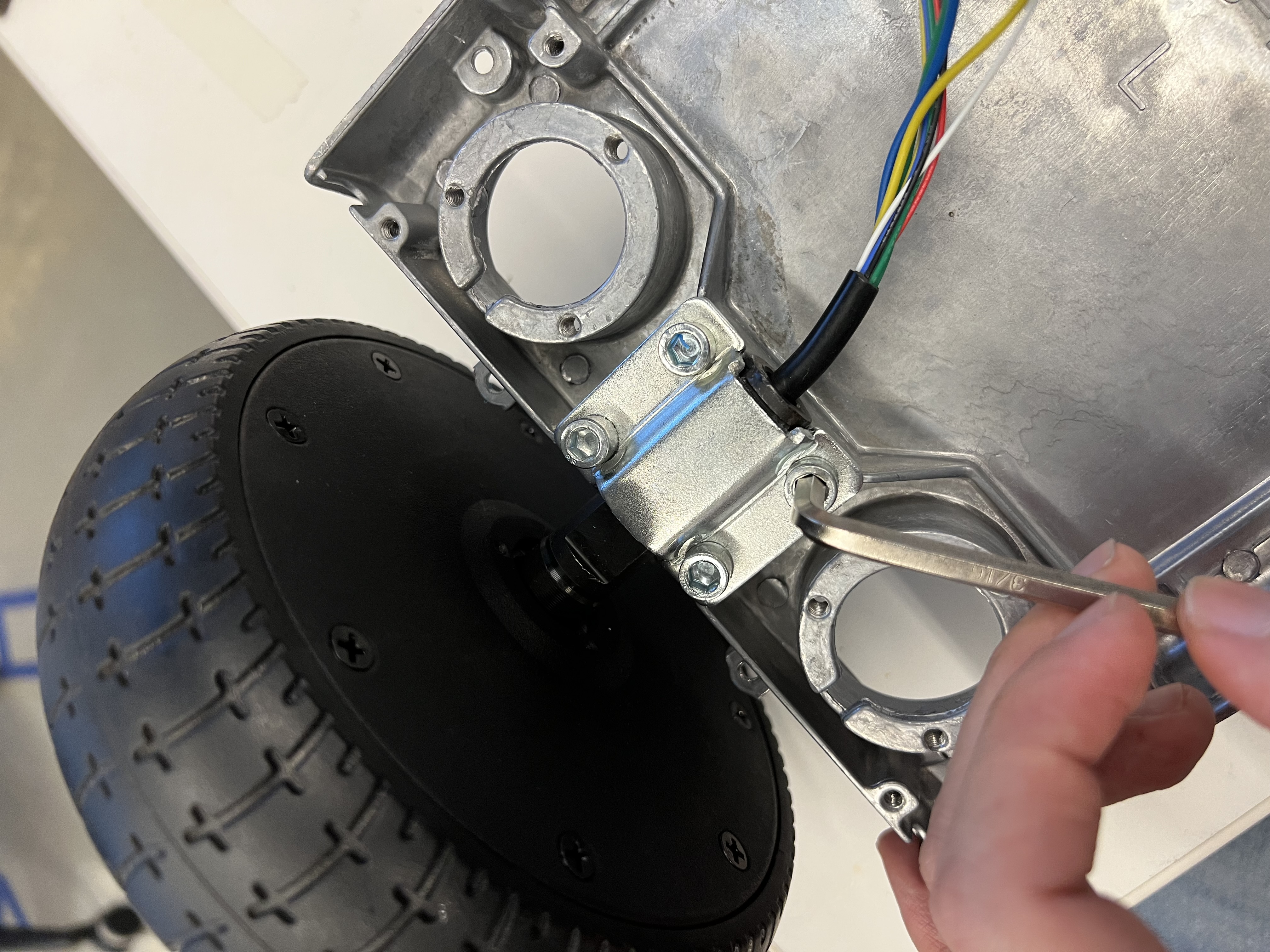
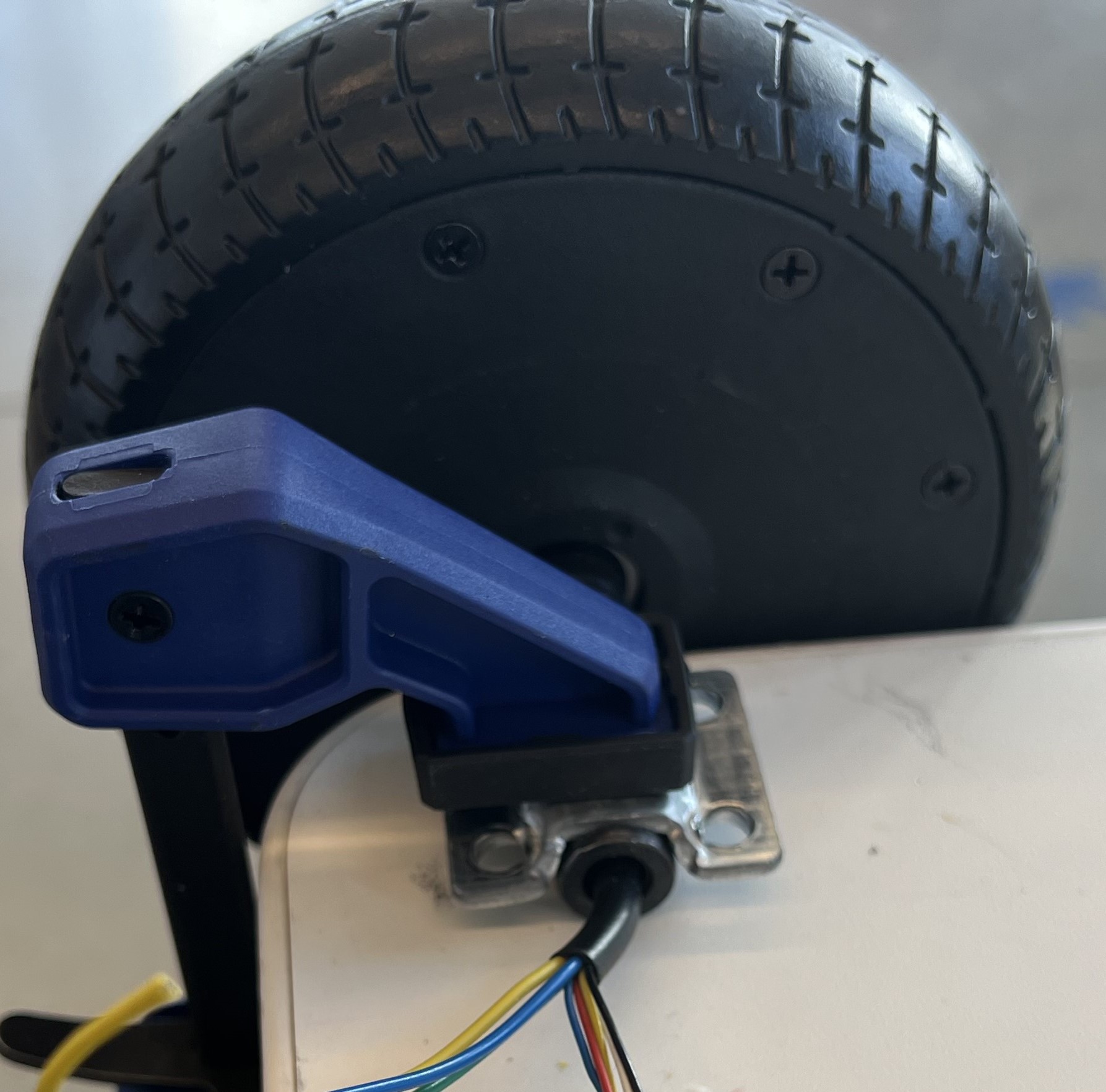
A1. Clamp the Wheel
Remove one wheel from the hoverboard with a hex key. Clamp the axle firmly to a desk — the wheel must be free to spin but the axle must not move.
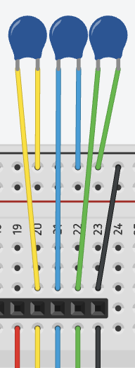
A2. Build the Filtering PCBs
Solder three 22 nF capacitors onto each breadboard (one per motor). These filter noise on the hall sensor lines. See the ODrive hall state post for details.
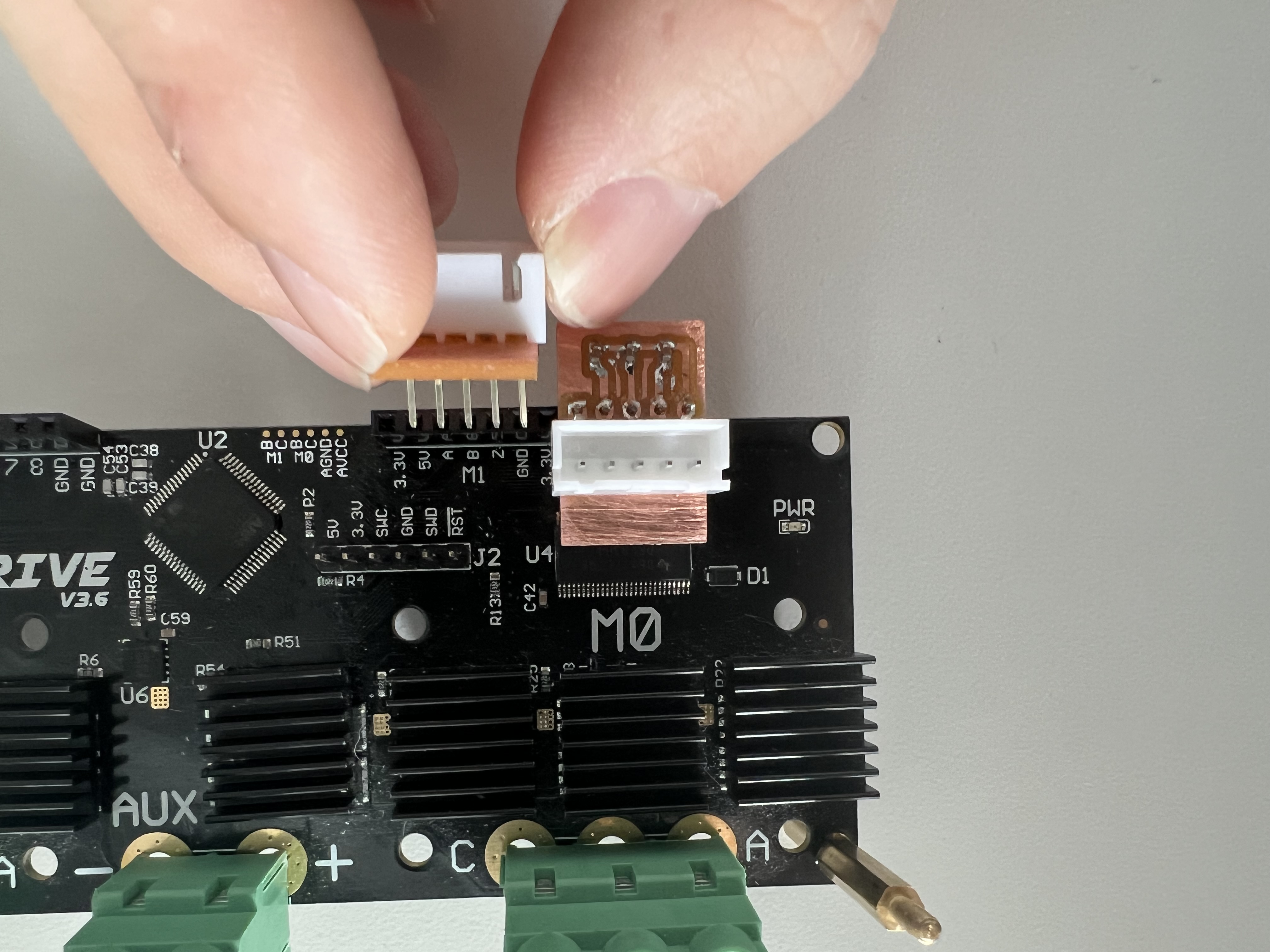
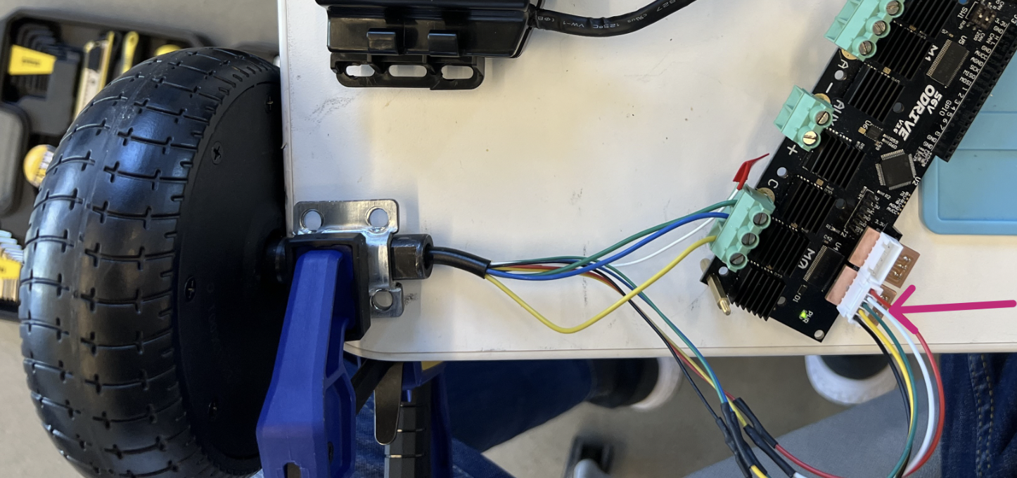
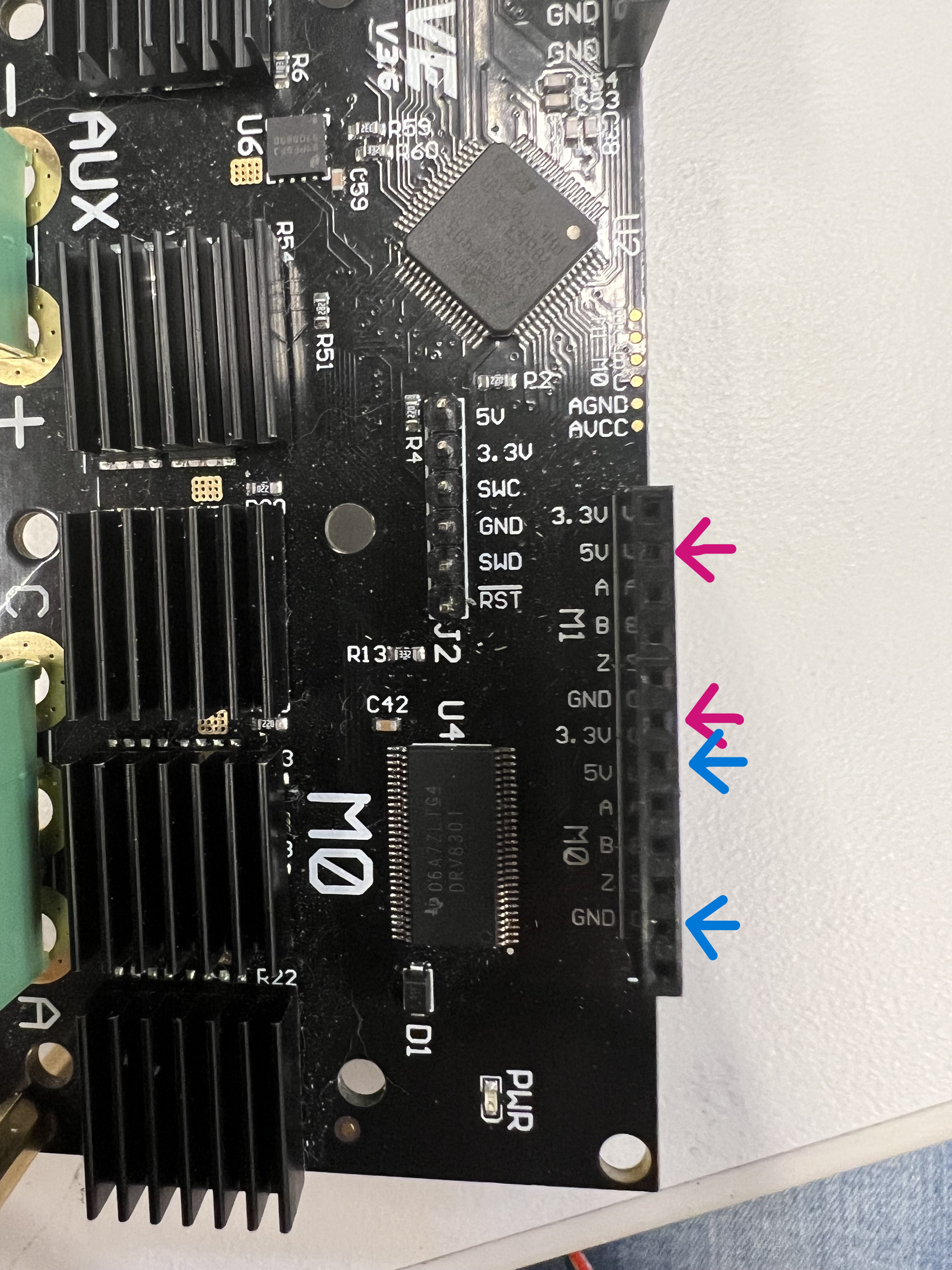
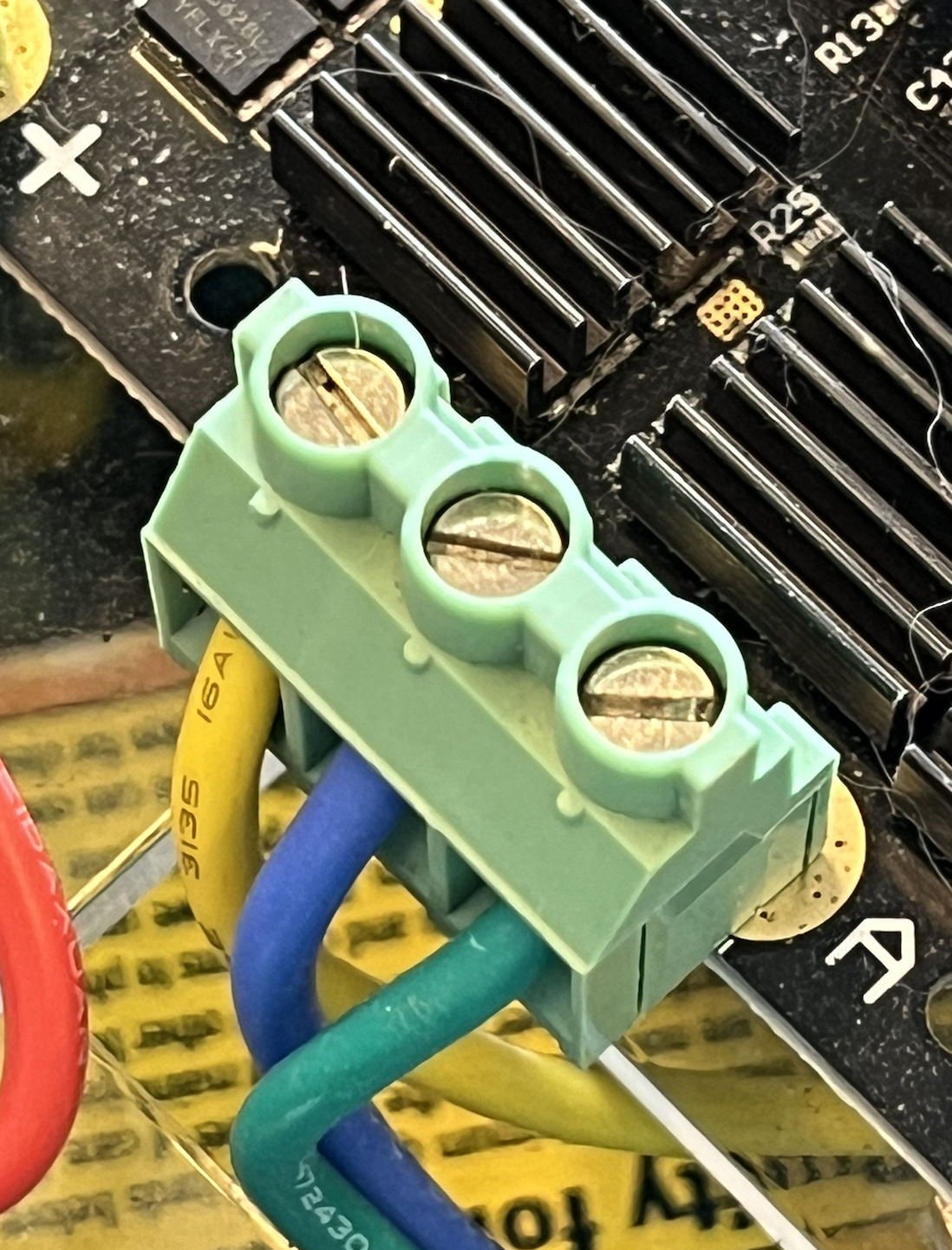
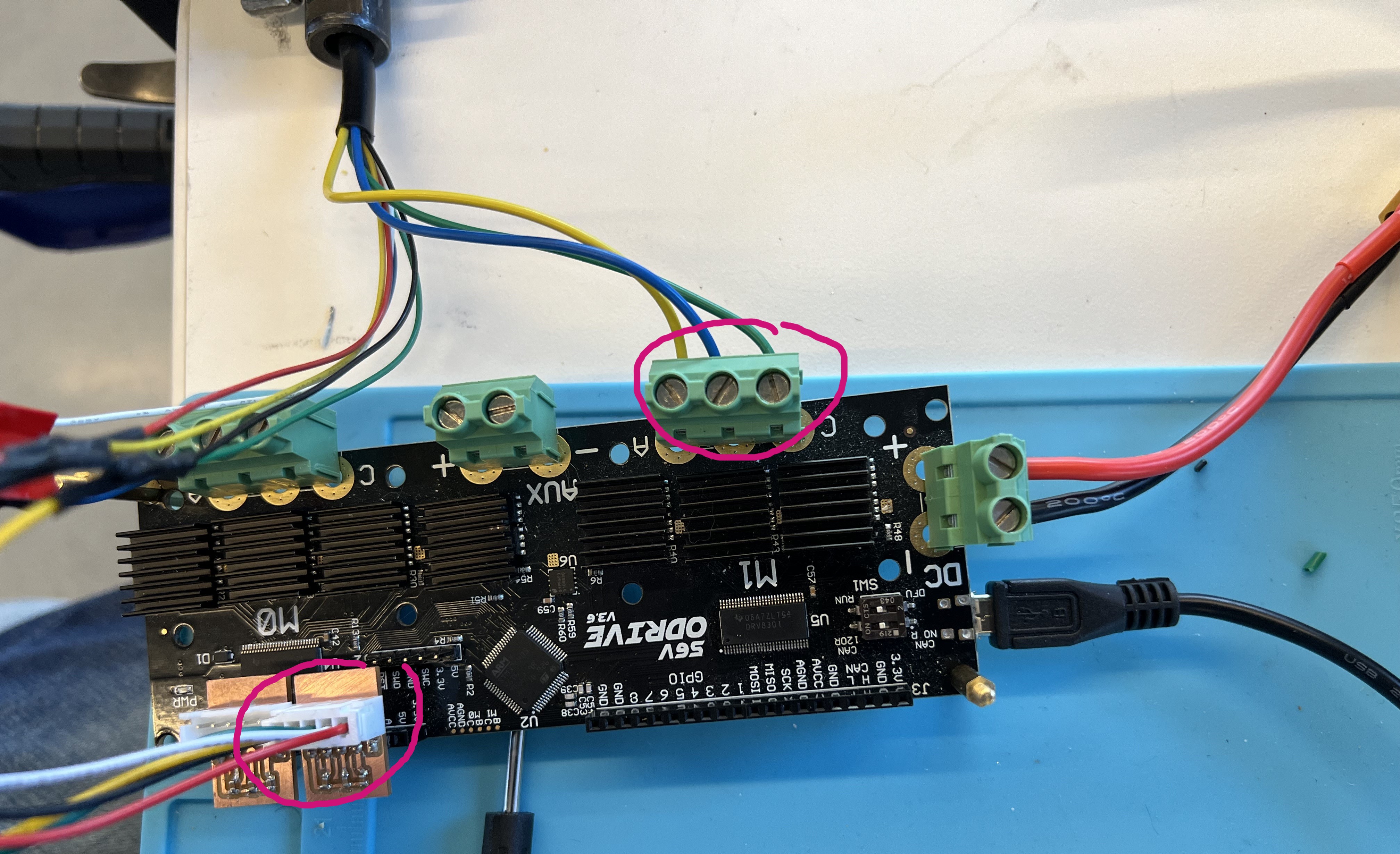
A3. Insert Hoverboard Wires to ODrive
Insert hoverboard wires (yellow, blue, green) from the motor to the ODrive board. You may need to solder wire extensions if the wires are too short. Cover any dangling white wires with electrical tape.
The five PCB pins go from GND to 5V — the red wire connects to the 5V pin labeled on the ODrive.
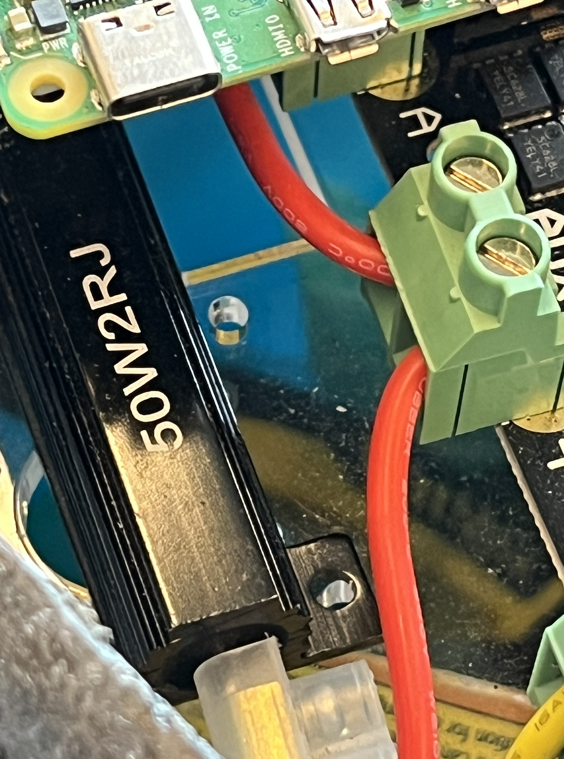
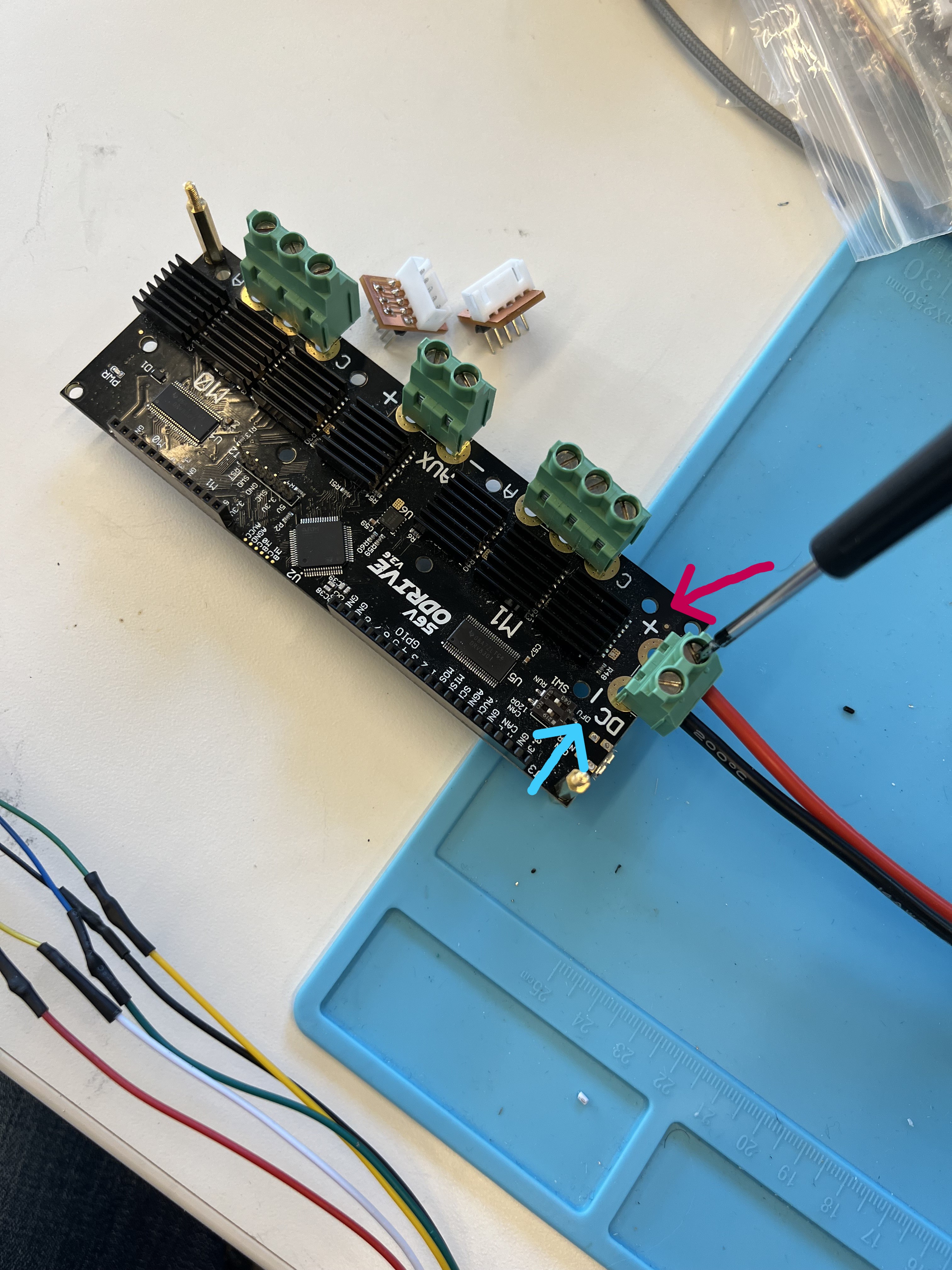
A4. Insert Brake Resistor into ODrive
Insert the brake resistor into the designated slot in the middle of the ODrive board.
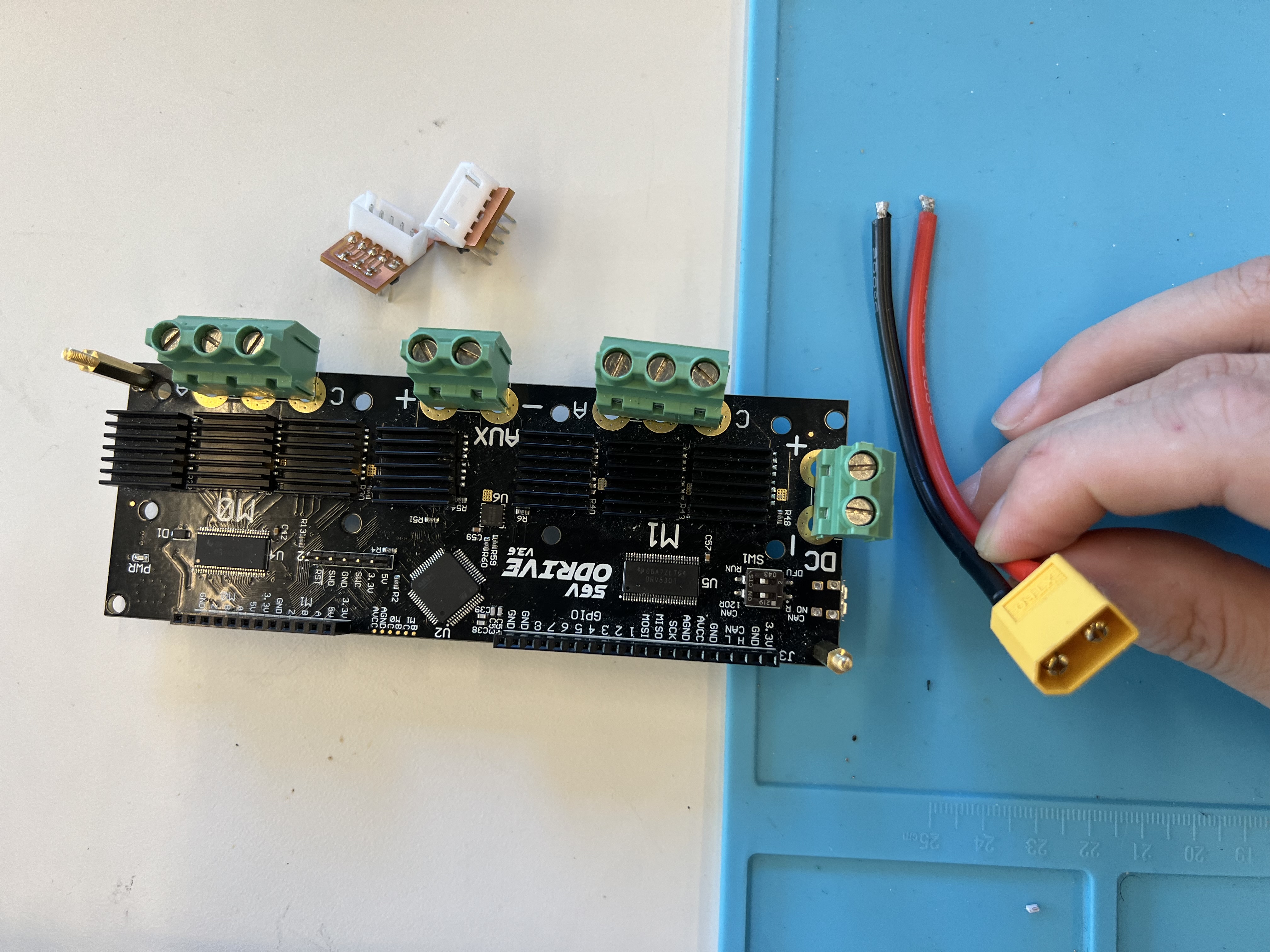
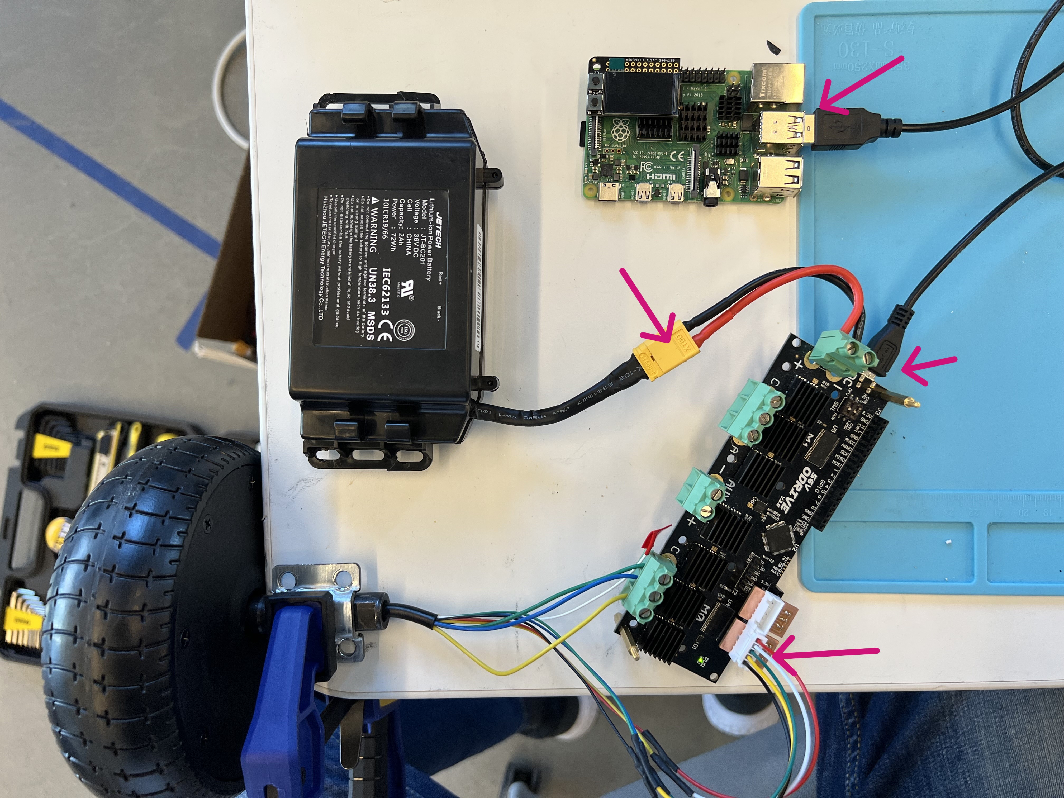
A5. Connect XT60 Power Cable
Connect the XT60 power cable from the hoverboard battery to the ODrive power input.
Polarity
Red wire = positive, black wire = negative. Reversing polarity will damage the ODrive.
A6. Connect ODrive to Raspberry Pi
Connect a micro-USB cable from the ODrive to the base Raspberry Pi.
A9. Plug In Power
Connect the hoverboard battery. The ODrive power LED should light up.
Part B: Software Calibration
B1. Flash the Raspberry Pi Image
Use the Raspberry Pi Imager to write the class image to an SD card, then boot the base RPi.
B2. SSH into the Raspberry Pi
The IP address is displayed on the miniTFT screen after boot.
B3. Download the Lab Config File
curl -LJO https://raw.githubusercontent.com/FAR-Lab/Mobile_HRI_Lab_Hub/main/Lab3/mobilehri_config.json
odrivetool restore-config mobilehri_config.json
Note
Ignore warnings about parameters not being loaded — you will recalibrate the motors anyway. ODrive parameters may vary between hoverboard models; consult the ODrive hoverboard guide if needed.
B4. Open ODrive Tool
The terminal should show Connected to ODrive xxxxxxxx and a >>> prompt.

B5. Calibrate Axis 0 (First Wheel)
Wait for the motor to beep and spin briefly (~10–15 seconds), then check for errors:

Check for errors under axis0. If you see an ILLEGAL_HALL_STATE error, check that the filtering PCB is plugged in correctly. See the ODrive Hall State troubleshooting thread for more help.
If no errors, save and reboot:
B6. Test Axis 0
odrv0.axis0.requested_state = AXIS_STATE_CLOSED_LOOP_CONTROL
odrv0.axis0.controller.input_vel = 2   # 2 turns/second
Note the spinning direction. To stop:
B7. Calibrate Axis 1 (Second Wheel)
Warning
Unplug the battery before swapping wheels. Remove the first wheel's JST connector and phase wires, then connect the second wheel to axis 1.
Reconnect the second wheel's hall sensor JST to the axis 1 filtering PCB port and screw the phase wires into M1.
Plug in power and reconnect with odrivetool, then:
odrv0.clear_errors()
odrv0.axis1.requested_state = AXIS_STATE_FULL_CALIBRATION_SEQUENCE
dump_errors(odrv0)
Check errors under axis1. If no errors:
Test axis 1:
odrv0.axis1.requested_state = AXIS_STATE_CLOSED_LOOP_CONTROL
odrv0.axis1.controller.input_vel = 2
odrv0.axis1.controller.input_vel = 0
odrv0.axis1.requested_state = AXIS_STATE_IDLE
Both wheels calibrated — proceed to Assembly.